
Product Page
433 MHz RF Signal Strength Detector Student Projects
₨ 8,500
[yith_wcwl_add_to_wishlist]
Need some help?
Contact Us
Product Ships in
2-3-business Days
Payment Methods:
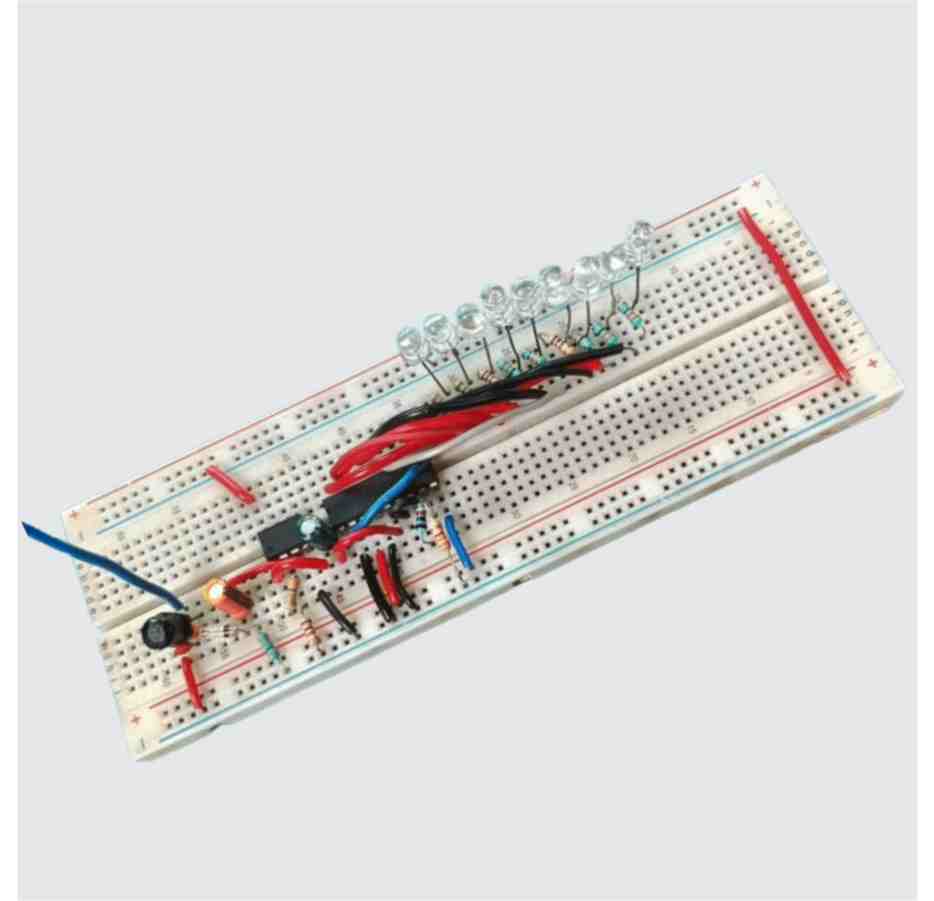
433 MHz RF Signal Strength Detector Student Projects in Pakistan
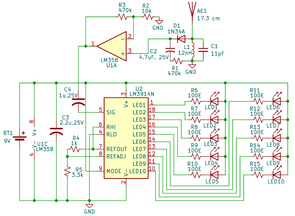
The input is taken from a 17.3 cm antenna in the form of small signal bursts, connected with 433MHz tuned LC circuit for amplification of the signal, then the amplified signal is passed to 1N34A germanium diode which converts those signal bursts into a measurable DC voltage, which is sent to LM358 op-amp. The amplified output from the op-amp is then transferred to LM3914 display IC’s input which showcases the LEDs as a bar graph according to the signal strength.
| Parts List |
| Semiconductors U1 – LM358 dual op-amp U2 – LM3914N LED display driver IC D1 – 1N34A germanium diode LED1–LED10 – 5mm LEDs (any colour as desired)Resistors(All ¼-watt, 5% carbon film) R1 – 470kΩ R2 – 10kΩ R3 – 470kΩ R4 – 1kΩ R5 – 3.3kΩ R6–R15 – 100Ω(10 Nos.) Capacitors Miscellaneous |
Learning points
- Learn to make an RF signal detector using LC circuit and discrete components.
- Learn the concept of gain in an op amp.
- Learn to visualise analogue signals using LEDs without digital processing.
- Develop practical debugging skills and awareness of noise and grounding issues in analog circuits.


