Product Page

Build Your Own IR Audio Communication System
₨ 9,000
[yith_wcwl_add_to_wishlist]
Need some help?
Contact Us
Product Ships in
2-3-business Days
Payment Methods:
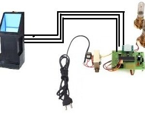
Build Your Own IR Audio Communication System Student Projects in Lahore
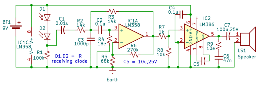
The receiver circuit, Fig. 2, uses the IR receiving channel, by which the optical signal is received, and then converted into the electrical signal using a band pass filter. LM358 is a dual op-amp, which has advantages of high gain, and internal frequency compensation. It can be used in a single power supply and has a wide input voltage range. Thus, LM358 can be used as a band pass filter in this circuit. It is configured with a range of frequency from 160Hz to 11000Hz using appropriate values of resistors and capacitors, filtering out other frequency signals and noise. This filtered signal is still weak and not sufficient to drive a speaker or headphone. Therefore, LM386 is needed to amplify the filtered signal and then drive the speaker to work normally.
The tested range for this circuit is approximately 4 metres. It can vary according to the environmental conditions, such as ambient light and sunlight.
| Parts List |
| Transmitter circuit: Semiconductors IC1 – LM386 audio power amplifier D1,D2 – IR emitting diodeResistors(All ¼-watt, 5% carbon film) R1,R2 – 2kΩ R3 – 100kΩ R4 – 10Ω R5 – 1kΩ R6 – 47Ω Capacitors Miscellaneous Receiver circuit: Resistors(All ¼-watt, 5% carbon film) Capacitors Miscellaneous |
Circuit Diagram
Learning points
- Learn to make wireless audio transmission systems using discrete components.
- Learn the concept of a bandpass filter and gain in an op amp.
- Learn the concept of IR transmitting and receiving diodes.
- Develop practical debugging skills and awareness of noise and grounding issues in analog circuits.